ASTM F2028: Preventing Glenoid Component Failure in Total Shoulder Replacement
Total shoulder replacement, also known as total shoulder arthroplasty (TSA), has become increasingly common with more than 50,000 surgeries performed per year in the US and expectations for this number are that it will continue to increase. There are numerous reasons why patients undergo total shoulder replacement surgery, including forms of arthritis, severe bone fractures, and/or excessive soft tissue damage.
Originally, the objective for shoulder replacements was to relieve pain after non-surgical approaches were exhausted. As the materials, implant design, and surgical procedures advanced, the objective transformed into not only relieving pain but restoring function and increasing range of motion in the joint.
Total shoulder replacement designs
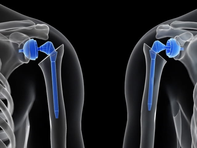
There are many different total shoulder arthroplasty implant designs in which both of the main components are replaced (humeral and glenoid components); however, there are two categories that these implants fall under, anatomic and reverse shoulders.

Both of these configurations, like most orthopedic implant devices, have their challenges once implanted. Typical failure modes for TSA include:
- Infection – Infection caused by the surgical procedure itself.
- Rejection – The body does not have a desirable reaction to the newly implanted device. It is recognized as foreign and the body rejects it through numerous immune system responses. This is also commonly caused by fretting and corrosion of modular devices that release harmful metal ions into the body.
- Fracture – Fracture to any of the device components such as the humeral stem, polyethylene glenoid, and humeral liner backing. Disassociation between mated components and fracture to the patient bone can occur.
- Instability – The humeral and glenoid components can experience retroversion and/or anteversion or humeral component offsetting. Poor bone adhesion or insufficient bone amounts can also lead to instability.
- Aseptic Loosening – One of the most common failures is loosening of the glenoid component.
Before these devices are brought to market, they must be subject to various rounds of testing to prove that they are safe and not vulnerable to the listed failure modes. Biocompatibility, mechanical interlock, mechanical fatigue, fretting corrosion, porous coating evaluation, and loosening testing are some of the tests performed for TSA devices. The FDA published the Class II Special Controls Guidance: Shoulder Joint Metal/Polymer/Metal Nonconstrained or Semi-Constrained Porous-Coated Uncemented Prosthesis document to provide direction for evaluating these devices. In addition, the following ASTM standards were created to assess the performance of different device components.
- ASTM F2028 – Standard Test Methods for Dynamic Evaluation of Glenoid Loosening or Disassociation
- ASTM F1829 – Standard Test Method for Static Evaluation of Anatomic Glenoid Locking Mechanism in Shear
- ASTM F1378 – Standard Specification for Shoulder Prostheses
- ASTM F1044 – Standard Test Method for Shear Testing of Calcium Phosphate Coatings and Metallic Coatings
- ASTM F1875 – Standard Practice for Fretting Corrosion Testing of Modular Implant Interfaces: Hip Femoral Head-Bore and Cone Taper Interface
Most of these standards are comparable to other total joints such as hip and knee with few specific details pertaining to shoulder components. However, the ASTM F2028 standard is specific to shoulder replacement designs and often referred to as the “rocking horse” test. This method provides direction to dynamically evaluate both anatomic and reverse shoulder configurations.
ASTM F2028 test method
The objective of ASTM F2028 is to evaluate the susceptibility of the glenoid component to loosening by quantifying the edge liftoff or pivoting of the component before and after cyclic testing. For both anatomic and reverse configurations, the devices should be in their final manufactured state with any polyethylene parts having been sterilized according to the manufacturer’s specifications.
The glenoid component is assembled into a bone substitute, typically polyurethane with density ranging between 25-30 lbs/ft3 (closely representing the average strength of glenoid cancellous bone), using standard surgical techniques. If cement is used in preparation, it is important to allow for curation.
Anatomic shoulder testing
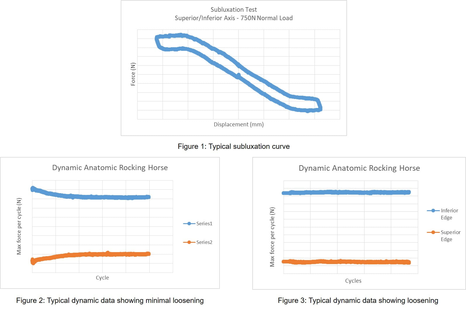
Two subluxation tests are performed prior to cyclic testing to quantify the shear force and displacement needed to sublux the humeral head off the glenoid component. Using a biaxial test frame, a compressive force (typically 750N) is applied to the glenoid component, through the humeral head and perpendicular to the glenoid plane, and then the humeral component is translated parallel to the glenoid plane along the superior/inferior (S/I) or anterior/posterior (A/P) axis of the glenoid component. This typically yields a shear force-displacement graph similar to Figure 1 (below).
Prior to cyclic testing, edge displacements or the amount of rocking seen in the glenoid assembly are measured. This is measured at three separate positions; the neutral location (location where no shear load is seen in the system when the humeral head is resting on the glenoid with preload), 90% of the subluxation translation in the superior/anterior direction, and 90% of the subluxation translation in the inferior/posterior direction. Cyclic testing is then performed in deionized water at 37C, typically between 1-2Hz, for 100,000 cycles or until failure has occurred. The test is a displacement controlled function with a distance of 90% of the superior/anterior and inferior/posterior subluxation translation measured in the subluxation test. This will typically result in a peak force versus cycle graph as shown in Figures 2 and 3 (below). Figure 2 shows no decrease in peak load typically indicating a firmly fixated implant while Figure 3 shows a decrease in peak force typically indicating loosening of the glenoid component.
Variations to these parameters can be made such as an increased number of cycles or performing a force control test rather than displacement control; however, such changes may deviate from ASTM F2028. Following completion of 100,000 cycles, the same edge displacement measurements are taken again for pre- to post-test comparison. A minimum of three specimens is suggested for this method.
Reverse shoulder testing
Static tests are not needed prior to cyclic testing when evaluating reverse shoulder constructs. Similar to the anatomic setup, there are pre-test edge displacement measurements performed. These measurements are made while simultaneously applying a shear force of 350 N parallel to the glenoid plane and an axial compressive load of 430 N through the center of rotation, perpendicular to the glenoid plane. While loaded, displacement measurements are made in both the shear and axial compressive directions as illustrated below.
The load is removed from the construct and measurements are taken again. This is repeated for a minimum of 3 cycles. After these initial measurements, cyclic testing is performed in air with fan cooling and/or with light lubrication. A compressive force of 750 N is applied through the humeral liner while the glenoid is rotated in the superior/inferior axis about its center of rotation, for a minimum of 10,000 cycles or until glenoid component failure occurs. A minimum rotation of 45 degrees is required (± 22.5°). Following cyclic testing, edge displacement measurements are repeated. Similar to the anatomic approach, a minimum of three specimens should also be tested. In the current standard, ASTM F2028-17, acceptance criteria are not given for either the anatomic or reverse with regards to edge displacements. Failure is determined by disassociation of the glenoid insert.
Custom methodology
Element has developed custom test machines for total shoulder arthroplasty testing, including two options for anatomic rocking horse testing. Each has an electromechanically actuated horizontal (in reference to the bench top) linear translation and a method to apply a joint compressive force perpendicular to the glenoid plane. The humeral head is attached to the horizontal axis and provides the superior/inferior or anterior/posterior translation.
The two test machines differ in the method used for applying this force. One machine has a dead weight system approach making use of hanging weights. The other uses electromechanical actuation, enabling custom, variable-loading scenarios.
The test machine used for reverse shoulder testing is also a biaxial electromechanically actuated machine. The horizontal axis is a rotary axis while the vertical axis is linear. Again, both of these axes are controlled enabling custom loading/displacement profiles.
Custom fixturing has also been implemented to allow for various designs and sizes of implants and for measuring edge displacements. For anatomic testing, the humeral head is typically cemented to a support fixture which bolts to the test frame’s horizontal sled. The glenoid and bone substitute assembly is machined to fit our custom cradle. The cradle allows for alignment in the anterior/posterior direction through the use of set screws while supporting the superior/inferior ends. The cradle also contains machined slots for the DVRT sensors used in measuring the edge displacements. In order for these measurements to be made, custom 3D printed platforms are manufactured for each implant. These platforms mimic the glenoid component geometry and can be fixed to the glenoid edges with adhesive. The DVRT sensors can then rest on these platforms and measure edge liftoff pre, post, and during cyclic testing (below, photograph 1).
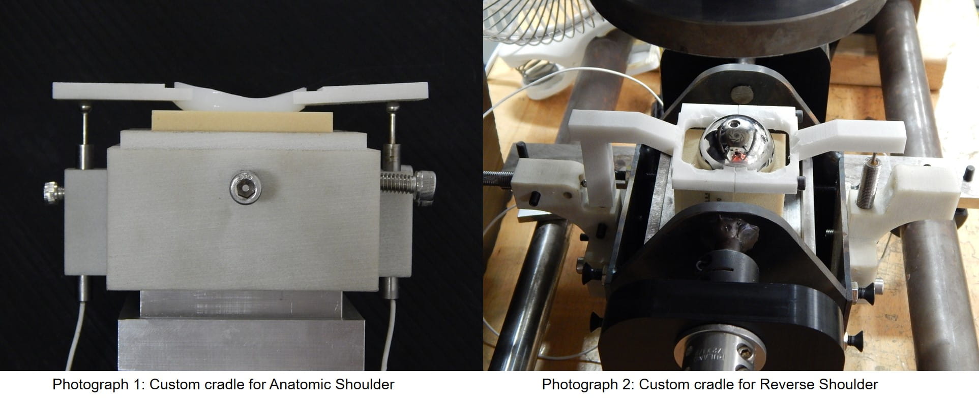
Similarly to the anatomic approach, when testing the reverse configuration, we use a custom made cradle that allows for rotation of the glenoid/bone substitute assembly. The cradle has attachments for DVRT sensor incorporation. Dissimilar to the anatomic method, these attachments allow for two DVRT sensors at each implant edge instead of one. ASTM F2028 requires the reverse configuration to have edge measurements to quantify both the axial liftoff distance and the displacement in the shear direction. Custom 3D printed DVRT platform attachments are designed for each implant and attached through a clamping technique or by use of an adhesive (above, photograph 2).
Conclusion
With the projected increase in total shoulder arthroplasty procedures, Element has pioneered methodologies to evaluate these devices and mitigate the risk of glenoid component failure. As the market continues to demand new technologies, the ability to modify and customize these tests methods is critical. Alongside methodology development, Element partners with our customers and standards organizations to meet their needs and ensure success.
If you have questions about our medical device services or how we can assist with your testing needs, contact our experts today.Find related Resources
Related Services

Foot, Ankle and Shoulder Replacement Implant Testing
With a wide range of services, we are a single source provider for foot, ankle, extremity and shoulder implant testing.

Test Protocol for Medical Devices
A protocol and plan will mitigate your risk, prevent confusion, set clear expectations, and preserve the necessary information for future reference and use.

Preventing Fretting Corrosion of Orthopedic Devices
The human body is a corrosive environment that can compromise the performance of orthopedic devices. The test methods outlined in this article aid in preventing fretting corrosion in your device designs.
Medical Device Testing
As a comprehensive testing partner, you’ll enjoy the benefit of a single supplier source for all of your testing needs, from mechanical testing and environmental simulation to EMC and wireless device testing.
